|
|
How to rebuild a crankshaft |
|
|
Right,
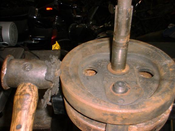
now you’ve made the stand this what you do with it. To split the crankshaft, firstly put the stand in the vice with the two bits pointing upwards. Place the crank with the timing side shaft facing upwards, on to the stand, there is no need to use the clamp that you made just yet! Firstly, undo the screws and remove the locking plates these can be a bit stubborn to get off, but you can insert a screwdriver under them and gently praise them off, taking care not to bend them as you will re-use them. Using a long ratchet or breaker bar undo the nut, the reason that you put it in the stand this way up first is because BSA cranks are keyed on the primary side of the crank. With the nut undone get a copper/ hide mallet and strike the timing side flywheel on the side, try to use one sharp tap rather than lots of little ones, the flywheel should then break off its taper and can be removed. |
||
|
|
||
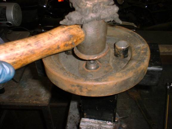
| When you have removed this flywheel, you can take off the connecting rod and the bearing cage and rollers, now you can remove the crankpin, by turning the crank over in the stand and undoing the nut on the remaining flywheel, then simply give the crank pin a sharp tap with the mallet on its threaded end. | ||
|
|
||
|
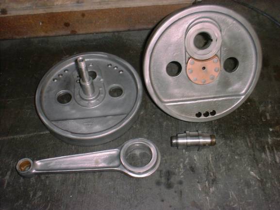
Now the crank is split, you should clean up all the components, personally I bead blast them and then use a “Scotch” pad or wire wool, the reason I use a two step process is because if you just bead blast them they tend to rust rapidly, if they are given a bit of a polish is this tends to make them a bit more rust resistant, besides the fact it looks pretty!!! This picture below shows the standard that you should try to achieve |
||
|
|
||
|
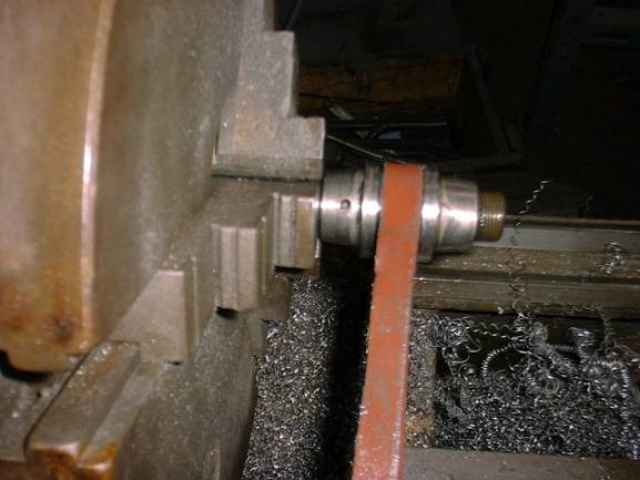
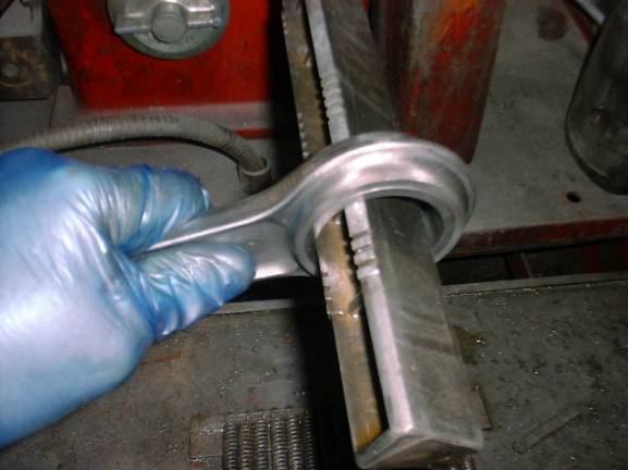
The reason that you give everything such a good clean is that the longer you handle the components, the longer you have to notice any defects, if you just give them a quick clean you may miss a slight crack in the flywheel or the loose rivet on the shaft. Now the components are clean, you can now decide on the best course of action to rebuild it, you can ignore all of this if you have a new crankpin and rod set! As we are trying to save you money we’ll do this the cheapest way! Firstly decide where most of the wear is, if you have a micrometer you can check the wear on the rollers, but you usually find that they are worn 0.002 inch or 0.003 inch and the rod race in the connecting rod has a tiny bit of wear along with a couple of pits in the crankpin (this is what I usually find!) if there is a lot of pitting or deep witness marks where the rollers have sat stationary on the crankpin for a long time and the acids in the oil from combustion have etched the surface of the crank pin, you may as well throw it away and get another one! What you have to decide is where most of the wear is and concentrate on trying to remove the wear or damage on that particular component and just basically refresh the surface on the other component. To clean up the crankpin, the best way is to put it in the lathe and with emery tape and polish the surface this can also be achieved by clamping the two ends of the crankpin in the vice and using the emery tape in a backwards and forwards motion, making sure in this instance that the tape does a full loop of the pin so that it cleans it up evenly this will actually take quite a while so don’t be scared of taking off too much, obviously doing it in a lathe is a lot quicker this should be done irrespective of the pin looking in good condition as you will be using a long one piece roller and there will be a microscopic ridge where the ends of the two separate were running alongside each other. See photo below |
||
|
|
||
|
To clean up the connecting rod race, it is a bit more difficult for the amateur to achieve. I personally use a honing machine but I’ve got a big workshop!! You can use a spring type hone running at a slow speed but this does not remove any slight ovality in the race a better method is to use a Delapena hone or better still take it to an engine reconditioners and get them to do it. Basically you are trying to get a good fit with the new rollers and restore the running clearance on the big end, usually you will find that the 0.001 inch oversize rollers won’t fit in there straight away, and you have to make the decision to remove a bit more metal on the most worn/ damaged surface. In some instances it may pay you to take the whole lot to an engine reconditioners and explain to him the contents of this section and let him sort it out for you. The cost shouldn’t be much, I have all the machinery and it only takes about a quarter of an hour to sort it out. The photo below is of the connecting rod being cleaned up on a horizontal honing machine. With regard to the tapers in the flywheels, check them for ridges near the outside edge where the crankpin has pushed up a sliver of metal when it was initially tightened, if one is visible you should try to remove it by gentle filing, taking care not to damage any other part of the taper, the tapers sometimes wear when the engine is used as a brake, one flywheel will try to ride over the other and this movement over a period of time will cause the taper to wear. You can also check the amount that the flywheel grips the crankpin, by looking for a wavy line in the taper, another way is to put some engineers blue on the taper and turn it a few times and see that it has been removed evenly. There is no real way on a BSA to machine the tapers as this would be too close to the shoulder on the crankpin and you couldn’t be sure that it wasn’t only gripping just on the shoulder, Old M20 cranks are cheap so it would probably pay you to obtain another set in this instance. Don’t even think about using grinding paste unless you want to make matters worse! |
||
|
|
||
|
A
nice finish on the connecting rod race should be a nice crosshatched finish
at about 120 degrees. Now
would be a good time to put a new small end bearing in, you can do this by
using a socket that is slightly smaller that the outside diameter of the
bushing but still has a large enough diameter to not jam in the bush as you
press it and on the other side another socket whose inside diameter is
larger than the outside diameter of the bush but not too big as you want it
to sit on the “eye” of the connecting rod. Simply sandwich the rod
between the two sockets and tighten the vice, the bushing should be slowly
pressed out into the larger socket Hey Presto and its out! To put the new
one in simply squeeze it in using the vice, don’t forget to drill the oil
hole in it then, just ream it out. Now you are ready to reassemble the crankshaft! Firstly place the woodruff key in the crankpin and ensure that there are no traces of oil or grease on the tapers of either the crankpin or its mating part on the flywheel, if there is the pin will not seat properly in the taper, it would be as if it is floating on the oil and will never stay tight where you put it so it should be cleaned with thinners or acetone, needless to say that you have blown out the crankpin and the oil way in the mating flywheel before you start this and made sure that everything is scrupulously clean!! Place the crankpin in the flywheel and tighten up to 100 ft lbs, I find that if you do it in stages it moves when you do the final tightening, when it is torqued up try on the lock washer and see if it lines up, if it doesn’t you can tighten it up a little bit more until it does, but before you do try both lock washers on both ways round, it may fit as the lock washers are sometimes slightly different. If the lock washer doesn’t line up, never slacken it to get it to line up! |
||
|
|
||
|
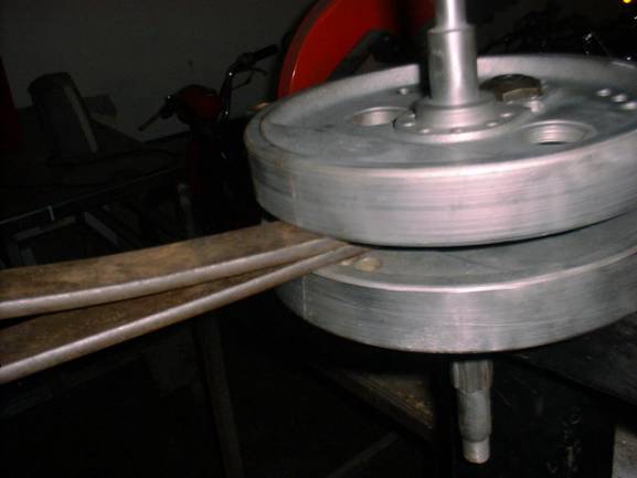
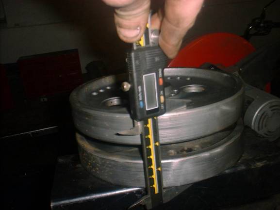
Now after putting the bearings in and the rod on, you can place the other flywheel on top and just nip the nut to about 20 ft lbs, then place the truing clamp as close to 90 degrees away from the crankpin as you can, this needs tightening up pretty tight to get the flywheels in line then you must slacken it off and have it at about 15 ft lbs this initially trues the flywheels then lets them pull together evenly (so that the flywheels don’t just pull together by the crankpin and leave the side opposite so tightly clamped that they don’t pull in evenly) Now all you have to do is tighten it up to 100ft lbs and once again check that the locking washer lines up. This is your crankshaft now assembled. Now the fun bit!!! (Not) It’s time to true the flywheels, this is quite hard to explain and you’ll find that the more you do the easier it becomes, but it does help to do it in a set order. The first thing you’ll need is a lathe or a crank truing stand. If you have a lathe you will need two centres, you could machine up another one from round bar, one in the tailstock and leave the one you’ve just machined in the chuck! First things first you must make sure that the flywheels do not run out across their outside edges, it is best to do this on the stand when you’ve tightened up the nuts, you will find a digital vernier caliper best for this, all you have to do is take a measurement across the flywheels by the crankpin, and another one directly opposite, then another at 90 degrees to the last and then another directly opposite this one, this will tell you where the run out is, if one side is too high you can squeeze it in the vice or with a G clamp, the main reference point for all these measurements is the crankpin as all sides of the flywheel should be in line with it. If the opposite side to the crankpin is too small a measurement you can open up the gap between the two flywheels with a pair of tyre levers levering them apart. See the photos below to see what I mean. |
||
|
|
||
| The picture below shows where the measurement should be taken, then at 90-degree intervals around the rim, if the measurement is larger than on the crank pin side, you must squeeze the flywheels together, and if the measurement is smaller you must spread the flywheels with the tyre levers. | ||
|
|
||
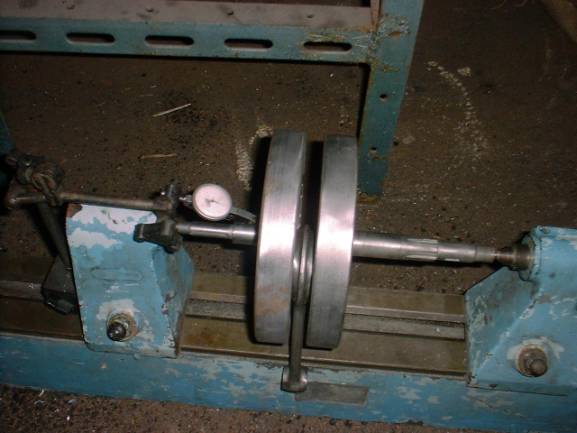
| When you have got the measurement to within about 0.002 inch or less, you can now put the crank into the lathe or truing stand to do the final truing. You should place the crank in the stand and adjust the tailstock so that the crank has no lateral play, in other words there should be no free play so the crank could move side wards and give a false reading and at the same time not so tight that it is squeezing the flywheels together. Now it is in the stand correctly positioned the following picture shows the crank in the stand. | ||
|
|
||
|
Place
your dial gauge on one of the shafts, this is the shaft that you now use to
index the run out from, you can use two gauges if you’ve got them as it
helps you understand why you have run out where you have it, but you can
still do it just as well with one. My own gauge is of the Verdict type but
you can also use the Mercer type, if you can get one that is calibrated in
0.0001 this is better as it allows you to see the run out sooner and as a
sweeping movement as opposed to a sudden “blip” from the needle. Now you must understand the types of runout. |
||
|
|
||
|
By
understanding where the misalignment is you can correct it by carefully
hitting the flywheel rim in the appropriate place, as to how hard you have
to hit it is a matter of experimentation, it is better to hit it not hard
enough than to hit it too hard and throw the whole assembly out too far in
the other direction. It is better to start off giving it a “sharp tap”
than to hit it with a “crack”. Sometimes with this jig you can get it to
within a couple of thousandths of an inch first time, and other times it may
take half an hour to get it spot on, it will always true up easier if you do
it in the logical way, by sorting out the run out on the flywheel edge, then
tackling the other types of run out.
The hardest type to get trued up is where one flywheel is higher than the other one, and by experience usually, the only way to sort this out is to split the flywheels and try again after using a little emery paper on the tapers hoping that it will allow the taper to reseat itself in the correct place, the picture shown below shows an exaggerated view of the taper problem. |
||
|
|
||
| By removing the burr you should hopefully allow the taper to reseat itself. | ||
|
This just about covers most of the problems encounters whilst crankshaft rebuilding. If you find that you can’t get the crank to run truer than 0.005 inch the problem could be that the flywheel is defective, and you may have to get new wheels. Usually you can true the crank to under 0.001 inch, but on an M20 you could happily run it with about 0.003 inch (the bearings will usually allow for this, but obviously the closer that you can get absolute zero the better, as the engine will be smoother. Good luck! If you have any problems regarding crankshaft rebuilding please do not hesitate to ring me on +44151 200 9161 (evenings) Thanks to Jake Plumb (for doing the drawings!) © Dave Plumb 2007 |
||